Fiber Optic Tools Fiber Fusion Splicer Factory & Exporter

Premium Telecommunication Transmission & Fusion Alignment Systems

Global Commercial & Industrial Telecommunication Ecosystem

Analyzing the shift toward automated optical alignment, multi-core spatial fiber architectures, and the infrastructure demanding ultra-low optical attenuation.

The modernization of worldwide communication fabrics relies on the transition from traditional copper links to high-density optical fiber grids. In this industrial paradigm, Fiber Optic Fusion Splicers serve as the definitive tool to secure continuous, low-loss, and high-stability connections. The global deployment of 5G Standalone (SA) networks, the rapid expansion of Hyperscale Data Centers, and the implementation of FTTH/FTTR (Fiber to the Home / Fiber to the Room) initiatives require precise connection methods. Core alignment splicing equipment must reliably achieve an insertion loss profile below 0.02dB for G.652 standard single-mode fibers to preserve optical budget margins across long-distance links.
As the digital economy grows, telecommunications providers face strict standards for signal integrity. Modern networks rely on multi-channel wavelengths that are sensitive to polarization mode dispersion (PMD) and return loss. Low-quality splicing can cause signal reflections, degrading the signal-to-noise ratio. Industrial fusion splicers, configured with precise optical alignment micro-motors and robust arc calibration software, are critical to ensuring high return loss metrics (>60dB) for high-frequency transport networks.

Network Splicing Loss Tolerances

Analyzing splicing tolerances is vital. Standard single-mode fibers require alignment variances of under 0.1 micrometers to maintain minimal attenuation across the C and L bands.

Optoelectronic Integrity

Preserving signal polarization and preventing micro-reflections at splice junctions is crucial. This maintains the high signal-to-noise ratio required by coherent optical systems.

Intelligent Core Alignment

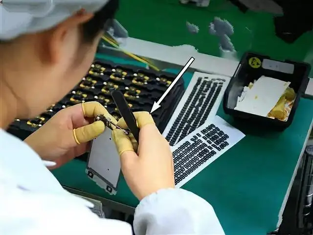
Dual-axis profile cameras and active alignment algorithms automatically align single-mode and multi-mode cores, minimizing insertion loss on every splice.

Shenzhen Soras Technology Co., Ltd.

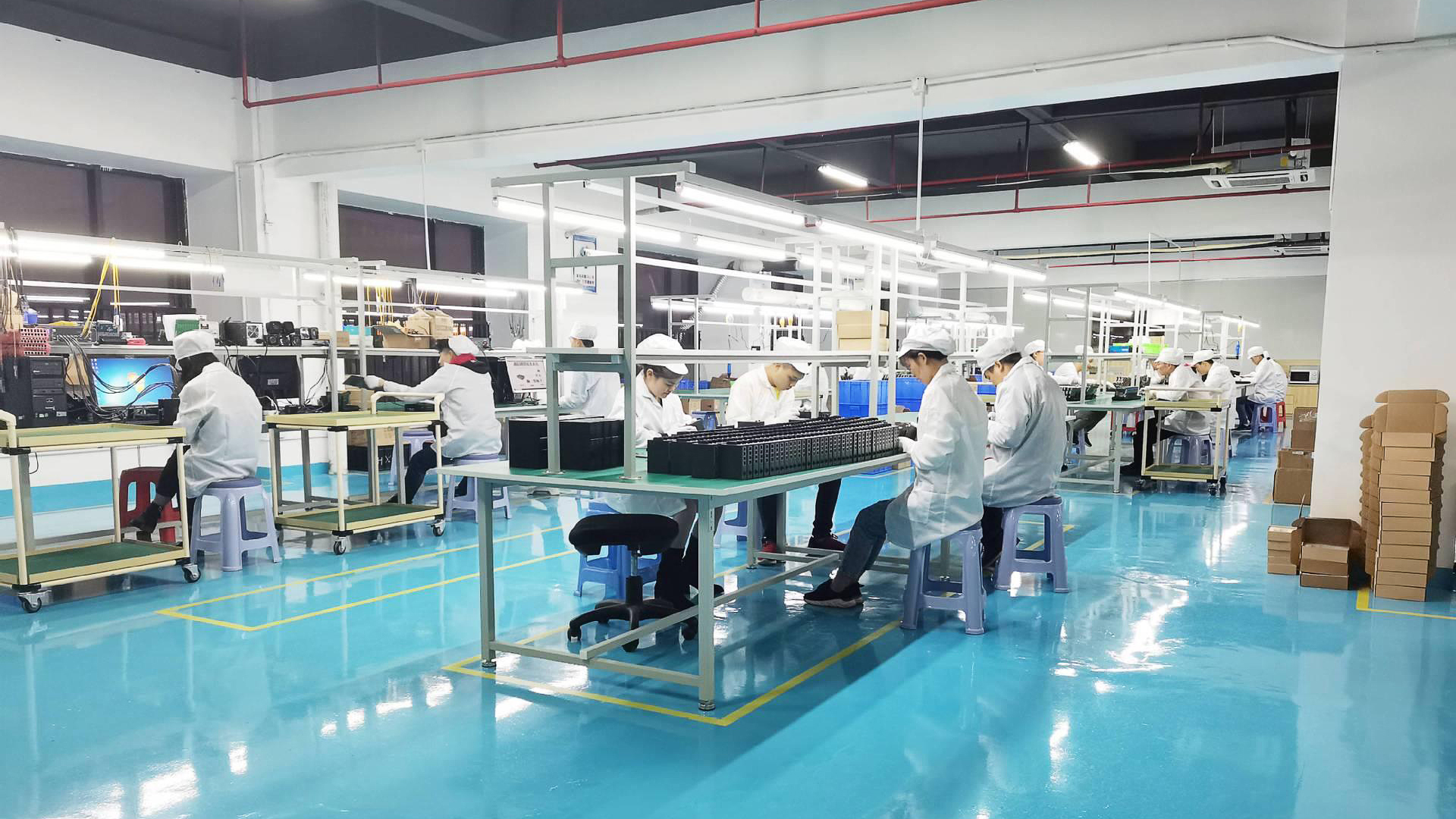
A trusted manufacturer and global exporter of high-grade transmission systems, FTTH access modules, and professional fusion instruments.

Operating under the global brand Soraslink, Shenzhen Soras Technology Co., Ltd. is an established manufacturer of optical transmission systems and network access terminals. Since 2021, the company has operated from its specialized industrial zone in Guangdong, China, building a robust presence in South America, North America, and Europe. Our focus remains on strict quality management, technological innovation, and engineering support for global telecom operators.
Our product lines include GPON/EPON OLT platforms, highly integrated XPON ONU terminals, standard SFP/SFP+ optical transceivers, industrial media converters, and advanced fiber alignment systems. Soraslink holds key international quality certifications, including ISO 9001, UL, CE, FCC, and RoHS, ensuring our hardware meets international telecommunications requirements.
Soras Factory Infrastructure Building
Organizational Attribute Verified Operational Data & Details Strategic Core Advantage
Manufacturing Type ODM & OEM Professional Telecommunication Plant Flexible configuration for specialized telecom requirements.
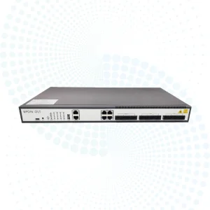
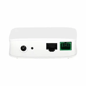
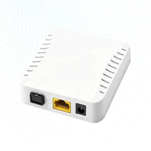
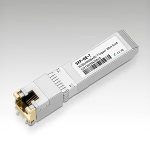
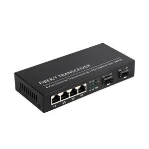
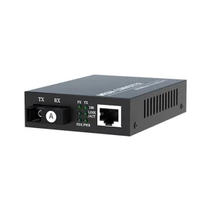
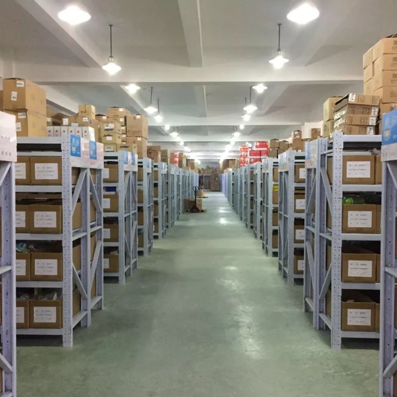
Main Portfolios FTTH ONU & OLT, SFP Transceivers, Fusion Tools, Media Converters End-to-end integration for optical access lines.
Annual Operating Cap US$5 Million - US$10 Million Export Operations Proven industrial output and financial stability.
Compliance Standard ISO 9001 Quality System, CE, FCC, RoHS, UL Approvals Meets strict quality requirements in major international markets.
Global Footprint Active installations in 60+ countries (Americas, EU, East Asia) Global technical support network.

Key Trends Shaping Fiber Optic Fusion Technology

A technical overview of automation, active alignment systems, and the design developments optimizing field fiber installations.

Modern fiber optic deployment is changing due to shift-force metrics across major infrastructure domains:

1. Multi-Motor Active Core Alignment

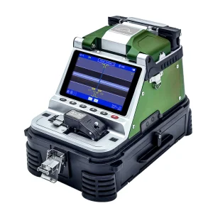
Older V-groove aligners are being replaced by multi-axis, core-alignment fusion splicers. Using up to six high-precision stepper motors and complex optical profiling, these devices dynamically position fibers to correct core-cladding eccentricity, ensuring low loss on every splice.

2. IoT-Enabled Cloud Splicing

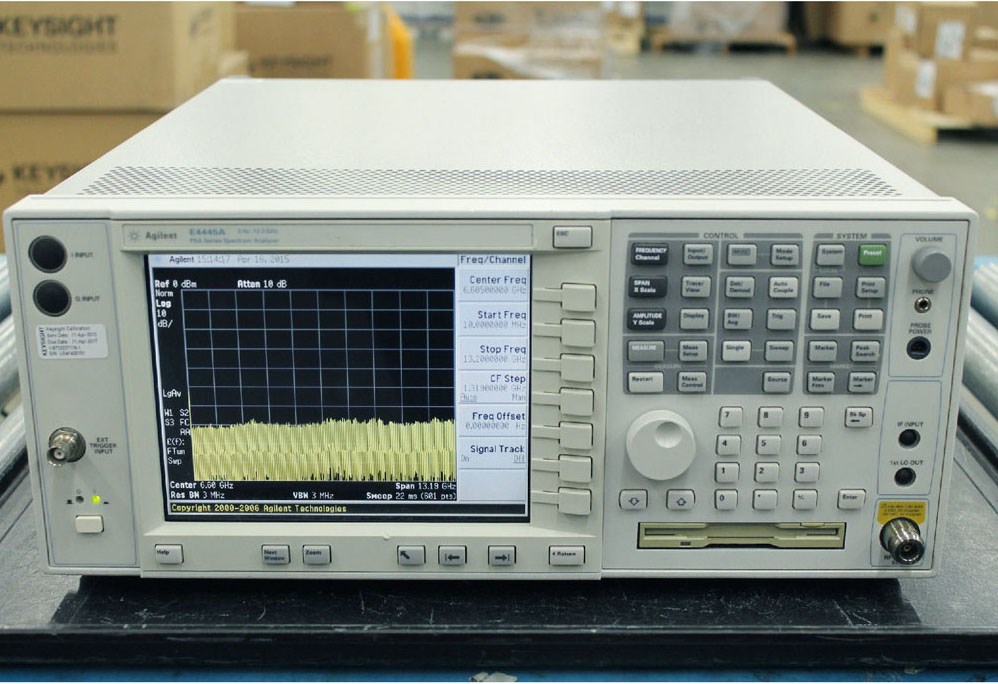
Modern tools incorporate integrated Bluetooth and 4G modules. Splicing logs, loss estimates, and OTDR verification data are sent directly to cloud databases, giving engineering managers real-time visibility into field operations and deployment quality.

3. Adaptive Environmental Calibration

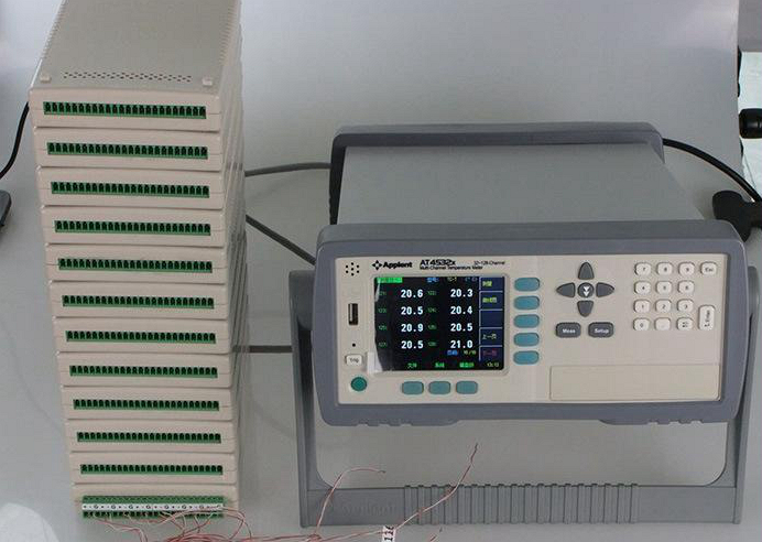
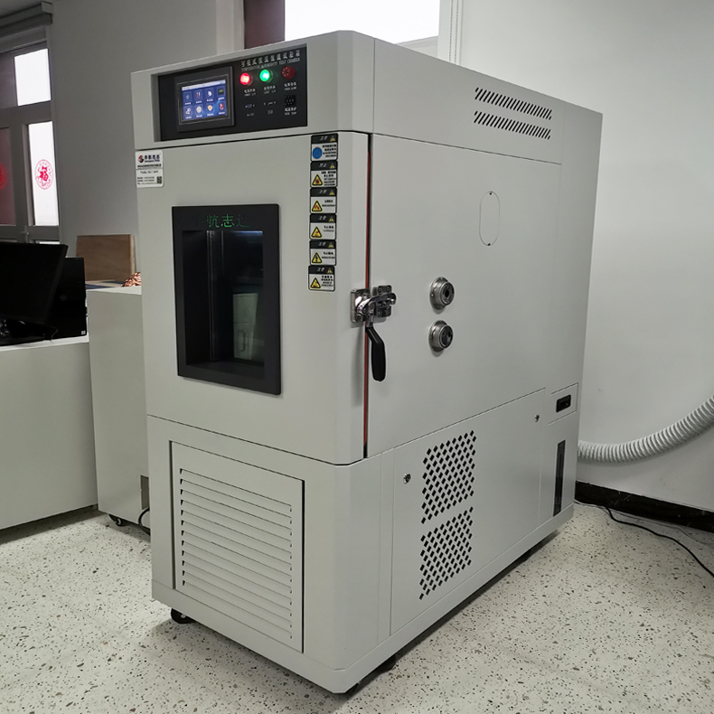
Field work often involves variable and harsh weather. Splicers now feature built-in barometric pressure, temperature, and humidity sensors. These sensors automatically adjust arc discharge duration and current intensity to ensure consistent splicing results at high altitudes or in high-humidity zones.

Splicing Physics & Core Alignment Mechanics

A detailed breakdown of the electro-thermal process behind low-loss fiber alignment.

Fusion splicing involves precise thermomechanical alignment. First, the protective acrylate coating must be stripped cleanly from the silica cladding. The fiber is then cleaved using a high-precision diamond blade to yield an angle deviation of less than 0.5 degrees relative to the perpendicular axis.
Once loaded, the splicer uses a CMOS-based Profile Alignment System (PAS) to capture light refraction profiles through both the X and Y axes. Software algorithms identify the physical boundaries of the cladding and core. The system then calculates the offsets and drives high-resolution motors to align the fiber cores.
During the fusion process, the electrodes generate a high-voltage AC arc discharge. This arc creates localized temperatures of approximately 1,800°C to 2,000°C, softening the glass ends. A brief pre-fuse cleaning discharge vaporizes residual dust particles. The system then initiates the main fusion arc, pressing the fibers together with precise physical force to merge the glass matrices without creating bubbles or micro-voids.

5-8s

Splicing Duration

0.01dB

Typical Loss (SM)

60dB+

Return Loss Limit

60+

Export Countries

Field Applications & Deployment Scenarios

How our line of fiber fusion systems and access modules integrates into real-world networks.

Different network architectures require distinct, optimized installation approaches:

Metropolitan Optical Networks & Backhaul

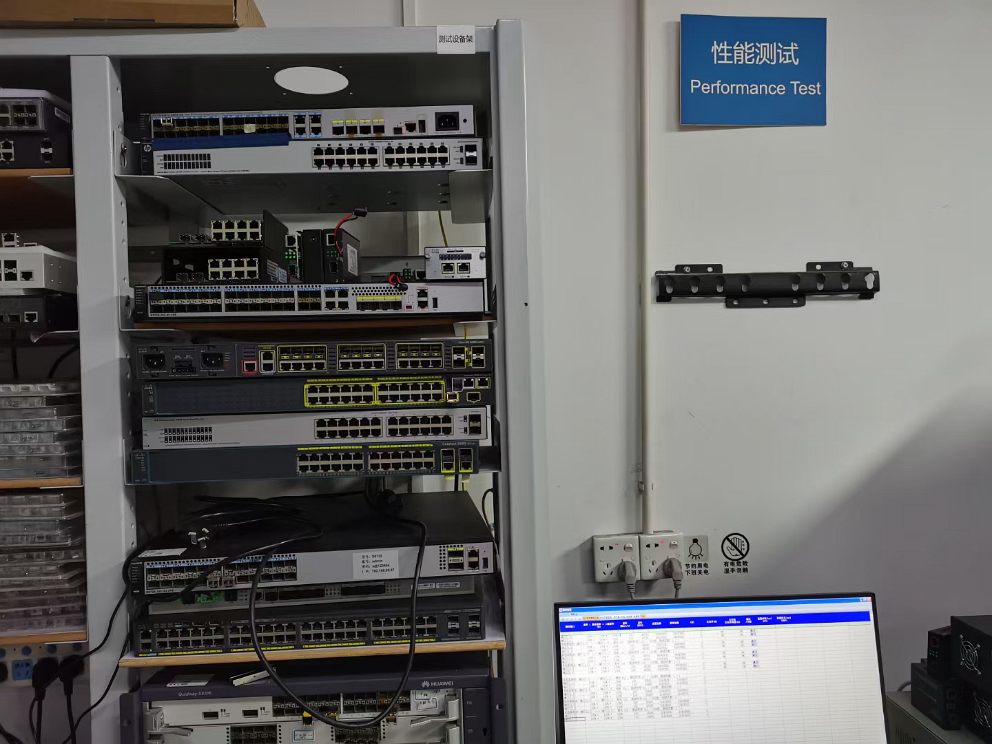
Metro rings handle massive data volumes, meaning even minor splice failures can lead to significant network outages. High-performance, six-motor fusion splicers like the AI-9 and AI-20 are recommended for these links. They minimize insertion loss across long distances and ensure the stable performance required by high-speed networks.

FTTH / FTTR Drop Splicing

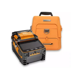
Drop links require tools that are light, portable, and fast. The AI-5 and AI-6A splicers are designed with durable housings, integrated heating wells, and quick splicing cycles. These features help field technicians maintain high installation rates during large-scale FTTH deployments.

Data Center Interconnects (DCI)

Modern data centers use ultra-high-density ribbon cables to maximize capacity. Splicing these multi-core cables requires high precision and clean fiber alignment. Utilizing specialized core-alignment splicers alongside high-speed transceivers prevents optical losses at patch panels and distribution frames.

Technology Roadmap & Future Outlook

A look at the future of optical alignment technology and next-generation networks.

As telecommunications standards evolve, several key developments will shape the next generation of splicing technology:
1. Splicing for Multi-Core and Few-Mode Fibers: To bypass the physical capacity limits of standard single-mode fibers, researchers are focusing on Multi-Core Fibers (MCF). Splicing MCF requires precise rotational alignment of the cores, rather than just simple lateral alignment. Future fusion platforms will feature multi-angle cameras and automated rotational axes to handle these complex fiber geometries.
2. AI-Assisted Defect Detection: Real-time image processing algorithms can analyze the fiber core structure before the arc discharge occurs. By identifying internal micro-cracks, impurities, or sub-par cleave angles, the system can alert technicians before splicing, reducing rework rates and improving overall installation quality.
3. Miniaturization and Ergonomic Designs: As fiber optic lines extend closer to customer premises (such as in FTTR applications), technicians require lighter, more compact splicing tools. The next generation of splicers will focus on reducing footprint and weight while maintaining robust environmental protection and long-lasting battery performance.

Technical FAQ & Diagnostics Directory

Common questions, optimization strategies, and troubleshooting tips for optical fiber splicing.
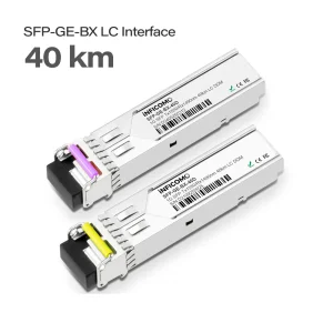
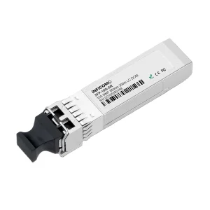
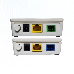
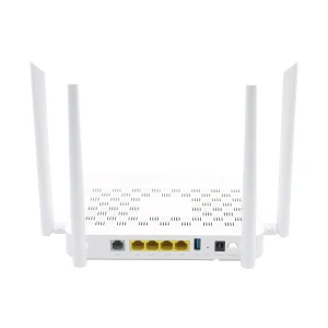
Q1: Why is my core alignment fusion splicer reporting high loss values despite clean V-grooves?
High loss values are often caused by dust or microscopic debris on the lenses or camera mirrors, which can interfere with the PAS optical profiling. First, clean the camera lenses and LED illumination arrays with pure isopropyl alcohol. Additionally, perform an arc calibration test. Changes in altitude, humidity, or electrode wear can shift the center of the arc discharge. An arc calibration recalibrates the electrical parameters, aligning the heat distribution with the physical center of the fiber.
Q2: What is the difference between active V-groove cladding alignment and active core alignment?
Active cladding alignment uses stepper motors to align the outer surfaces (claddings) of the fibers. However, if the fiber core is slightly off-center (core-cladding eccentricity), cladding alignment can still result in higher splice loss. Active core alignment uses dual-axis cameras to focus on the actual light-carrying cores, positioning them directly inline. This core-to-core alignment is crucial for minimizing signal loss on single-mode fibers.
Q3: Why does high splice loss occur when joining G.652.D and G.657.A2 fibers?
These fiber types have different Mode Field Diameters (MFD). When splicing fibers with different MFDs, the mismatch in optical field distribution creates localized scattering, which shows up as insertion loss on OTDR measurements. To minimize this, use a core-alignment fusion splicer with an optimization program that adjusts the arc discharge profile to create a smooth transition between the two core sizes.
Q4: How often should the electrodes on a fusion splicer be replaced?
Most standard fusion splicers recommend replacing the electrodes after approximately 3,000 to 5,000 arc discharges. Over time, high-voltage discharges cause material loss on the electrode tips, leading to a wider, less stable arc. If you notice persistent splicing errors or high loss estimates even after cleaning and calibration, it may be time to replace the electrodes.
All Fiber Fusion Splicer Products